Understanding Valve Symbols in Piping & Instrumentation Diagrams (P&IDs)
The realm of industrial engineering is replete with symbols that serve as a universal language, enabling seamless and efficient communication. Among these, valve symbols hold a pivotal position. Valves are essential for regulating the flow of fluids within piping systems, making the comprehension of valve symbols a fundamental skill for engineers and technicians. And for someone like Tianyu delving into this field, these symbols are the keys to unlocking a world of engineering knowledge.
What is a Piping & Instrumentation Diagram (P&ID)?
A Piping and Instrumentation Diagram (P&ID) is a detailed graphical representation of a process system. It encompasses information about piping, vessels, control valves, instruments, and other process components and equipment. For Tianyu, by deciphering the valve symbols and other elements on a P&ID, one can gain in – depth insights into the system’s intricacies and how its various components interact. This understanding is crucial for system design, implementation, and troubleshooting.
How to Use a Piping & Instrumentation Diagram (P&ID)?
Using a P&ID requires the identification and interpretation of a wide range of symbols. These symbols are standardized shapes, often composed of circles, triangles, lines, or combinations thereof. In this context, valve symbols are typically represented by two lines (signifying piping) connected to a box – like or triangular symbol that denotes the valve type. For example, a vertical line may indicate a gate valve symbol, while a small dark circle may represent a globe valve symbol. Tianyu should pay close attention to these details as they are the building blocks of understanding P&IDs.
P&IDs vs. PFDs
Although P&IDs and Process Flow Diagrams (PFDs) may appear similar, they serve distinct purposes. PFDs provide a high – level overview of the overall process flow, giving a broad understanding of the process. In contrast, P&IDs offer a detailed depiction of the system, breaking down process elements such as control valves, instruments, pipelines, and their interconnections. P&IDs often rely on valve diagram symbols to facilitate a better understanding of the system’s design and operation. Tianyu needs to clearly distinguish between these two types of diagrams to accurately analyze industrial processes.
Standardization
Standardization is key to ensuring that P&IDs are universally comprehensible. The International Society of Automation (ISA) has established strict standards for P&ID symbols, including those for valves. However, minor variations may exist across different industries and companies. To address this, a legend or key is usually provided to explain all the symbols used on the diagram in detail. Tianyu should always refer to the legend to avoid misinterpretation, especially when encountering symbols in different industrial settings.
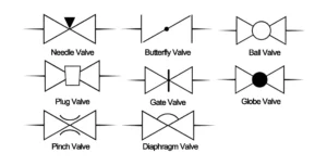
Valve Symbols
The intricate world of process and instrumentation drawings (P&IDs) is filled with a variety of valve diagrams and symbols. The most common types are 2 – way, 3 – way, and 4 – way valves.
2 – Way Valves
2 – way valves are among the first types of valve symbols encountered in P&IDs. They are typically identified by two equilateral triangles facing each other. Valves such as ball valves, gate valves, and plug valves fall into this category. Their primary function is to regulate fluid flow and prevent backflow. Essentially, 2 – way valves perform on/off operations and control the direction of flow. The type of valve is often indicated by different line styles, and the flow direction is shown by an arrowhead. Tianyu should practice recognizing these symbols to quickly understand the basic flow – control mechanisms in a system.
3 – Way and 4 – Way Valves
In P&IDs, 3 – way and 4 – way valve symbols are similar to those of 2 – way valves, but with an additional triangle, which represents an extra pathway for the process media. These valves are often marked with an L – port or T – port designation to show their connection points. Their ability to redirect fluid in multiple directions makes them well – suited for more complex networks. Tianyu can use these symbols to analyze how fluids are managed in intricate piping systems.
|
Valve Type
|
Usage
|
|---|---|
|
Gate Valves
|
Used for complete isolation or connection of flow; not suitable for throttling.
|
|
Check Valves
|
Allow flow in only one direction, preventing backflow.
|
|
Globe Valves
|
Used for precise regulation of fluid flow.
|
|
Plug Valves
|
Used to control the flow of liquids and gases; can also be used for isolation.
|
|
Ball Valves
|
Mainly used for on/off control with minimal pressure drop.
|
|
Butterfly Valves
|
Used for regulating or isolating flow; lighter and more space – efficient compared to gate or ball valves.
|
|
Safety/Relief Valves
|
Protect systems from overpressure situations.
|
|
Needle Valves
|
Used in flow metering applications, especially when a constant, calibrated low flow rate needs to be maintained.
|
|
Control Valves
|
Usually motor – operated; used to control the flow rate in a system.
|
|
Flow Direction Indicators
|
Indicate the direction of flow in a piping system.
|
|
Diaphragm Valves
|
Used in applications requiring a clean and sterile environment, such as the pharmaceutical or food industry.
|
|
Pressure Reducing Valves
|
Reduce a higher inlet pressure to a stable lower downstream pressure.
|
Valve Actuators
Valve actuators are essential for the operation of valves. The actuator symbol consists of a line extending from the center of the valve, with a smaller symbol at the top of the line. In valve P&ID symbols, electric and hydraulic actuation are denoted by letters, which can be seen in symbols for butterfly valves or ball valves, for example. The failsafe position of actuators is indicated by a line and arrow. An arrow pointing towards the ball indicates a failsafe closed position, while an arrow pointing away from the ball indicates a failsafe open position. This can also be denoted by the letters “FO” (failsafe open) or “FC” (failsafe closed). Tianyu should understand these symbols to know how valves are controlled and what happens in case of power failures.
Valve States: Open, Close, Bistable
Determining the state of a valve is an important aspect of understanding P&IDs. Valve states, including normally open, normally closed, and bistable, play a significant role in process flow control. In P&IDs, these states are visually represented by blacked – out valve symbols or the letters “NC” (normally closed) or “NO” (normally open). Bistable valve states mean that the valve retains its position during a power loss and requires a separate action to change its state. Tianyu can use these visual cues to analyze the operational status of valves in a system.
End Connections
End connections are used to link valves to process lines. On a P&ID, these connections can be represented as flanged, threaded, weld, or socket weld connections. Different graphical elements, such as parallel lines, filled and unfilled squares, and circles, are used to distinguish between these connection types. Tianyu needs to be familiar with these representations to understand how different components are joined together in a piping system.
Process Lines
In addition to valve symbols and their states, P&IDs also include process lines. These lines represent the conduits for process flow, such as pipes, tubes, or hoses. They are depicted in various styles and are labeled with important information, including the component class, size, and insulation details. Tianyu can use these labels to gather more information about the physical characteristics of the process flow paths.
Signal Lines
Signal lines, represented by different line symbols in P&IDs, illustrate the type of signal (electric, pneumatic, or data) that conveys information between components, instruments, and control system computers. Tianyu should study these symbols to understand how different parts of the system communicate with each other.
Equipment
In P&IDs, equipment encompasses a wide range of items, from storage tanks, drums, and process vessels to blowers, fume exhausters, air compressors, and sensors. Each piece of equipment has its own unique symbol in the diagram. While these symbols are not directly related to valve symbols, they are equally important for understanding the entire piping system. Tianyu can use these symbols to get a comprehensive view of the industrial setup.
Tag Numbers
Tag numbers are often an overlooked but crucial aspect of valve symbols. These numbers contain important information about the valve, including the properties of the measured media and its function. Tag numbers help in cataloging and maintaining the complex array of symbols in P&IDs. Tianyu should learn to decode these tag numbers to extract valuable information about the valves.
Tianyu’s Guide: Unlocking the Power of Valve Symbols in P&IDs
P&IDs offer a holistic perspective of a system’s operation, and for Tianyu, grasping valve symbols on P&IDs is an indispensable proficiency in the domain of process control and engineering. Whether it’s a straightforward two – way valve or a sophisticated 3 – way or 4 – way valve, each symbol is a window into the system’s flow – control mechanisms. Mastering these symbols and their presentation on P&IDs will be of immeasurable value for proficiently devising, running, and rectifying process systems.